Tuesday, June 11, 2019

Vibration Spectrum : Mixing Frequencies

When two frequencies are present in a machine and a cause and effect relationship is not present, the high frequency will be riding the low frequency and the Fast Fourier Transform (F’FT) will yield spectral lines at frequency one and frequency two. If there is a cause and effect relationship and the two frequencies can mix together, the result is amplitude modulation. Without getting mathematical, amplitude modulation is a time varying amplitude. Amplitude modulation is caused when the equipment has some form of non linearity. This non linearity permits the amplitude of the two signals to add together when the signals are in phase, or subtract when the signals are out of phase. With amplitude modulation, the carrier frequency will be the frequency with the highest amplitude. The envelope of the varying amplitude will be the difference between the two frequencies. An FFT of these signals can yield spectral lines at frequency one, and frequency one plus and/or minus frequency two.

For example, suppose gear mesh frequency is modulated by gear speed, gear mesh frequency is 1200 Hz, and gear speed is 20 Hz. An FFT of this signal would then yield spectral lines at 1200 Hz, 1200 + 20 = 1220 Hz, and/or 1200 – 20 = 1180 Hz.

Descriptions of these frequencies are:
1. 1200 Hz is gear mesh frequency.
2. 1220 Hz is gear mesh frequency plus gear speed. This is a sum frequency.
3. 1180Hz is gear mesh frequency minus gear speed. This is a difference frequency.
4. The difference between 1200and 1220Hz, or 1200and 1180Hz is 20 Hz, and this is also a difference frequency.
5. The source of excitation, or the problem shaft or gear is usually expressed as a difference frequency.

Sunday, June 9, 2019

Vibration Time Wave form : Multiple Frequencies-Non Linear System(Frequency Modulation)

Frequency modulation is a time-varying frequency,as opposed to amplitude modulation, which is a time-varying amplitude. The lower frequency is the carrier, and the higher frequency is the modulator. The modulator is normally an excited frequency, and the source of excitation is normally the speed of the rotating unit.
Pulse Excited Natural Frequency
Frequency Modulation

Frequency modulation can be a series of high frequency bursts similar to a pulse, or the high frequency can occur periodically with a low frequency. Since the frequency response of an accelerometer is best at high frequencies, such problems may be best measured in acceleration. Frequency modulation occurs most often in impacts, such as defects on the inner race of cylindrical roller bearings, or when two shafts are rotating very close to each other. Frequency modulation can occur in screw compressors, vacuum pumps, and blowers when one shaft is bent enough to permit an impact once each revolution.

One last comparison should be noted to clarify the differences between a high frequency
riding a low frequency, amplitude modulation, and frequency modulation.

1. High frequency riding a low frequency - No looseness is present. High and low frequencies may be exact multiples of each other. No mixing of signals occurs. Changes in the phase have little or no effect.

2. Amplitude modulation - High frequency is the carrier; low frequency is the modulator. Signals go into and out of phase.

3. Frequency modulation - Low frequency is the carrier; high frequency is I the modulator.

Vibration Time Wave form : Multiple Frequencies-Non Linear System (Pulse)

A pulse is caused by a hit or an impact. Pulses fall into one of three categories: empty pulses, frequency modulation, and amplitude modulation.This occurs when excited or generated frequencies are not present. It is called empty because it contains no generated or excited frequencies. A pulse is identified by a series of spectral lines. The repetition rate of the pulse is equal to the difference frequency between the spectral lines. The empty pulse has a low level spectral line at shaft speed, and the amplitude increases with each succeeding harmonic.
Empty Pulse
Frequency modulation is a time-varying frequency. This frequency modulation can appear as a series of bursts or beats. Generated or excited pulses are usually caused by a once-per-revolution impact or excitation.
Generated or Excited Pulse

Vibration Time Wave form : Multiple Frequencies-Non Linear System (Sum and Difference Frequencies ) .

Another type of amplitude modulation occurs when one component is eccentric. One example of sum and difference frequencies is gear eccentricity. When one gear is eccentric or out of round, the amplitude of gear mesh frequency increases when the high place or places go into mesh. If the gear has only one high place, the signal amplitude will be higher once each revolution. In either case, amplitude modulation is caused by the eccentric gear. The associated spectra contain a spectral line at gear mesh frequency with side bands of gear speed. If the gear has more than one high place, then the difference frequency between the gear mesh frequency and the side bands is equal to the number of high places times the speed of the problem gear. If two high places are present, the difference frequency is two times gear speed. Three high places would generate a difference frequency of three times gear speed, four high places would generate four times gear speed, etc.

If the eccentric gear has not caused looseness, side bands will occur at gear mesh frequency
plus gear speed or multiples of gear speed. In other words, the side bands will be on the high side of gear mesh frequency. The frequencies add, in this case, because the phase relationship between the carrier and the modulator is constant. As stated earlier, the machine is behaving in a linear manner.
One Revolution of Gear with Four Eccentricities.
Sum and Difference Frequency with No Phase Shift.
Sum and Difference Frequency with Phase Shift.
When a gear or geared shaft system is loose, the looseness causes the modulator to subtract from the carrier because the two frequencies are out of phase. When the two frequencies are in phase, they add. Looseness causes an out-of-phase condition. Eccentricity is an in-phase condition.
If gear eccentricity has caused looseness (non linearity) associated with the problem gear, side band scan occur on both sides of gear mesh frequency. If looseness is the more severe problem, the amplitudes of the side bands will be higher on the low side of gear mesh frequency. If eccentricity is the more severe problem, the amplitudes of the side bands will be higher on the high side of gear mesh frequency. If looseness is the only problem, then the side bands occur only on the low side of gear mesh frequency.
The frequencies subtract when looseness is present because the phase relationship between the signals is not constant, which means the machine is acting in a nonlinear manner.
The principles described for gear mesh frequency apply to other generated frequencies such as blade or vane pass frequencies, bearing frequencies, frequencies from multiple defects, and frequencies from bars or corrugations on press rolls.

Vibration Time Wave form : Multiple Frequencies-Non Linear System (Amplitude Modulation ) .

Two or more independent frequencies can be mixed together if a machine has some form of non linearity or other problem. There are many forms and degrees of frequency mixing. Examples of amplitude modulation, sum and difference frequencies, pulses, and frequency modulation are discussed in the following sections.

Amplitude Modulation :
Amplitude modulation occurs when two frequencies are added together algebraically. Frequencies will not add in a machine that behaves in a linear manner. Therefore, a problem must exist before amplitude modulation can occur. There are several forms of amplitude modulation; one form is a beat. A beat occurs when the amplitudes of two frequencies are added together.

When the amplitudes of the two frequencies go into phase, they add together. Then, as the two frequencies go out of phase, the amplitudes subtract until they are 180 degrees out of phase. The two frequencies continue to go into and out of phase, forming a time varying amplitude signal called a beat.

Beat-Amplitude Modulation of Two Frequencies.

Amplitude modulation also occurs when two frequencies are not exact multiples
Two Similar Frequencies with Second Harmonic.


Beat of Two Similar Frequencies.

Vibration Time Wave form : Multiple Frequencies - Linear system

High Frequency Riding a Low Frequency :
When two independent frequencies are present in a linear system, they cannot add together in amplitude or frequency. When this occurs, the two frequencies mix, and the high frequency will ride the low frequency, At first glance, amplitude modulation appears to be present.


High frequency riding on low frequency
Since harmonics are not present and the high frequency is riding the low frequency, there is not
a cause and effect relationship. The two signals are generated independently. It is important to note that a high frequency which is an exact multiple of a low frequency will cause the amplitude of the high frequency peaks to be the same in each period of the low frequency. A high frequency that is not a multiple will cause the amplitude of the high frequency peaks to vary during each period of the low frequency.

Saturday, June 8, 2019

Vibration Time Wave Form : Square Wave


A special case to note is a single frequency with only odd harmonics present. The harmonics tend to cancel each other out, except for one positive and one negative peak per time period of the fundamental. The peaks have an amplitude equal to the sum of all the amplitudes added together.
A special case of odd harmonics is has only odd harmonics, and every other odd harmonic is
180 degrees out of phase. The resultant signal is a square wave. The amplitudes correspond to the amplitude of the fundamental divided by the harmonic number.

Single Frequency with Only Odd Harmonics.
Note that the signal is not exactly square, but has ripples. This is due to the fact that a limited number of odd harmonics are contained in the signal. A true square wave contains all odd harmonics, which cannot be truly simulated on a computer as a sum of the cosine functions.

Single Frequency with Only Odd Harmonics.
It may appear impossible for a piece of equipment to generate a square wave, but it is possible to generate a signal with square wave features. This can occur in a motor if the motor has a loose mount. If the mounting bolts are loose, the motor will tend to move up and down. If the motor moves up and is stopped by the mounting bolt, and then moves down and is stopped by the motor support, a square wave can be generated. If clipping occurs on both the top and bottom of a signal and the clipping is significant,the result will resemble a square wave.

Vibration Time Wave form : Clipping

CLIPPING :
A signal is said to be clipped when a slight amount of the positive or negative signal is flattened. The upper signal is an undistorted time signal. The lower signal is clipped at the bottom.
Clipped Signal
a clipped time signal and a spectrum from a motor
1800 RPM Belt Driving a Fan.

Such a signal can be generated when a machine goes against a stop in one direction and cannot move further in that direction for a small period of time. As the cycle continues, the machine moves away from the stop in a relatively linear manner. The signal is distorted because the time period for the negative and positive portion is not the same. Clipping is also a “form of distortion. The frequency spectrum contains very little harmonic content, because in order for harmonic content to be generated, the signal distortion must be repeatable.


Vibration Time wave form : Single Frequency With Harmonics .


A harmonic is some exact multiple of a discrete frequency. The discrete frequency,called the fundamental, is the first harmonic. The second frequency, which is two times the fundamental frequency, is the second harmonic. The second, third, fourth, etc., harmonics can be either in phase or out of phase with the fundamental.

The phase relationships between the fundamental and the harmonics are valuable in diagnosing problems in rotating machines. Failure to understand and use the time signal and harmonic phase can result in diagnostic errors .

A single frequency without harmonics will have one positive-going peak per time period. The number of positive-going peaks in one time period of the fundamental frequency identifies the highest number of true harmonics. This is true for a single frequency with harmonics only, and is true regardless of the phase relationships between the fundamental and the harmonics. The amplitudes of the fundamental and the harmonics determine the amplitudes of the positive-going peaks. However, the phase relationships of the harmonics to the fundamental determine the locations of the positive going peaks in the signal.
Single Frequency with an In-Phase Harmonic.
Single Freq. with a 180 Degree Phase Shift and Harmonic.

Single Freq. with a 180 Degree out-of-Phase Harmonic.
However, both positive-going peaks are at the top of the signal. This can only occur if the second harmonic is 180 degrees out of phase with the fundamental.

These phase and amplitude relationships hold true for linear systems. However, most real applications contain nonlinearities,called distortion. The distortion can appear in the signal as a phase shift in one or more of the harmonics. Distortion of the signal can also generate additional harmonics in the frequency domain which are not true harmonics of the signal. Therefore, the number of peaks in the time signal must be checked for true harmonic content.

Continuing with phase relationships, the next step is to observe a phase shift of 90 degrees.
Single Freq. with 90 Degree Phase-Shifted Harmonic.
A good rule to remember is that if the source of the harmonic is tied to the source of the fundamental, such as a fixed, geared, or bolted coupling, the harmonic should be in phase. If the source of the harmonic is not tied to the source of the fundamental, the harmonic should be out of phase.
Single Frequency with a Lower Amplitude Harmonic.
After seeing the effect of changing amplitude , one can identify the effect of changing the amplitudes in other ways. Changing amplitude only affects the amplitude of the composite peak. It does not affect the number of peaks or the phase relationship of the composite.
Single Frequency with Two Harmonics.
The addition of a third harmonic will now be examined, along with the effects of changing the phase and amplitude. Changing the amplitude changes the amplitude of the individual peaks, as with two harmonics. Three positive peaks per cycle are present, indicating the three harmonics.

Single Frequency with Only Third Harmonic.

Single Frequency with Two Harmonics.

Single Frequency with Two Phase-Shifted Harmonics.
The time domain signal is necessary to verify which harmonics are true and which harmonics are caused by distortion.


Friday, May 3, 2019

Vibration Time wave form : Single Frequency

SINGLE FREQUENCY
A single frequency is often referred to as a discrete frequency and is the simplest form of frequency data. The time signalof a single frequencyand the resulting frequency spectrum from the Signal Analysis Program. The time period for each cycle is 0.01667 seconds and the signal is sinusoidal.

Sinusoidal simply means the signal follows the sine function. Mathematically, the time signal is:

The reason for using the cosine instead of the sine is because the starting point at time zero of the fundamental is the highest point. The cosine is the same as the sine, except for a 90 degree phase shift. In the real world, the signal can start at any point between 0 and 360 degrees .


When the time signal is processed by the FFT, it is divided into the amplitudes and phases of the individual cosine and sine functions. When a spectrum is displayed, the plot is an amplitude plot of the frequencies. If a complex FFT is performed, both the amplitude and phase are available, but only the amplitude is displayed. In the introduction, the frequency spectrum was said to lose the phase. In actuality, it may not be lost. It is just not listed or is discarded. Unless the phase is retained and viewed, the time domain signal must be used to identify phase relationships.

To reconstruct the time signals from the frequency domain, a starting point must be selected. When time equals zero, the cosine starts at maximum amplitude and the sine starts at zero amplitude. It is more consistent to start at the maximum amplitude of all signals, so the signals add at a time equal to zero.
This is a cosine function with a 180 degree phase shift. In rotating machinery, data taken from opposite sides of a motor should be the same, except the phases of the fundamentals should be 180degrees apart. This obeys all laws of physics.
Single Frequency 90 degrees phase shift
Single Frequency 180 degrees phase shift

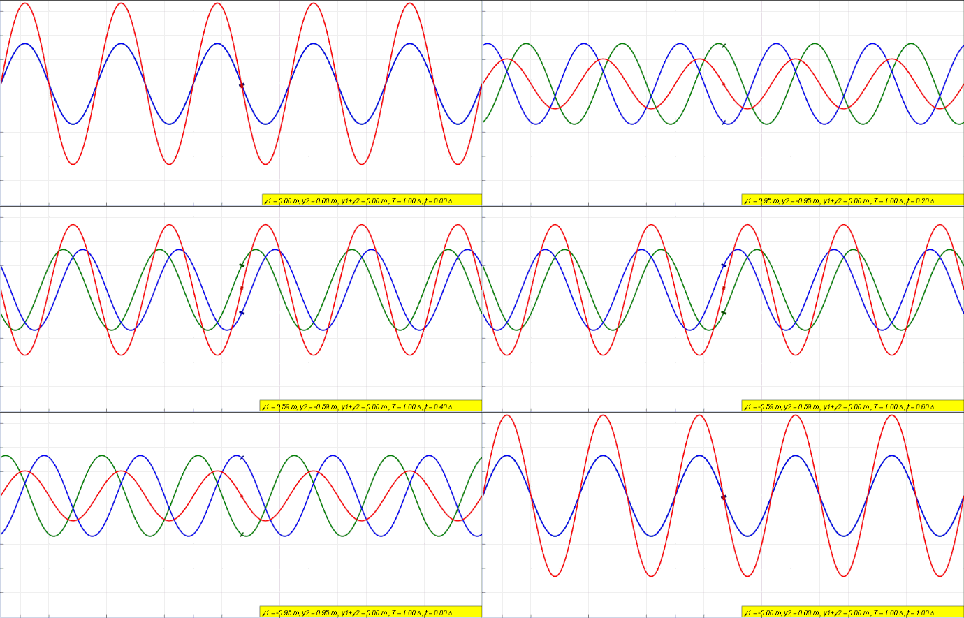
Amplitudes of signals in rotating machinery will add or subtract, depending on their phase relationships.
Two Frequencies signals 180 degrees out of phase to each other .
Two frequency signals equal in Amplitude & Phase

Thursday, May 2, 2019

Vibration : Time & Frequency Analysis

Accurate diagnosis of problems in rotating machines requires a thorough understanding of the time domain signal and the frequency domain spectra. Following are some of the reasons:

1. The time signal is a plot of amplitude versus time. This signal contains all frequencies, harmonics, and subharmonics. The phase relationships of these frequencies are also contained in the signal. Pulses, amplitude modulation, frequency modulation, truncation, and distortion are also present.

2. The frequency spectra are plots of amplitude versus frequency. These spectra contain frequency, harmonics, subharmonics, and sum and difference frequencies. The FFT produces the frequency spectrum from the time signal, based on electronic physics. However, during the process, some information is lost. For example, phase, true amplitude of pulses, nature of the pulses, bandwidth, and the various forms of modulation are not easily identified in the frequency spectrum.

3. A mechanical machine may not generate a fundamental plus harmonics in the same way as in the electronic world. However, a rotating machine does generate relatively linear signals when a linear problem exists, such as imbalance. A machine can generate a distorted signal as a result of a nonlinear problem. This distorted signal is a composite signal, as would be obtained after various frequencies and harmonics are combined.

4. For the above reasons, various time signals can produce the same frequency spectrum. This explains why the time signal must be considered. Costly errors in diagnostics and loss of credibility could occur if the time signal is not analyzed.

BASIC PHYSICS
 
All things in the universe obey the basic laws of physics. Vibration signals from rotating machinery must obey these same basic laws of physics. This is why we can take data from either side of a motor and receive the same results. (Some slight variations can occur in nonlinear systems because of transfer functions.) In a pure linear system, data taken in different directions around a motor should be the same, except for phase.
a sine wave is the plot of a circle against time. All complete circles contain 360 degrees and all complete sine waves contain 360 degrees. The phase of a signal can be anything from 0 to 360 degrees, depending on the reference point .
Before analyzing the time signal, an understanding of how frequencies add and subtract, and the effects of the phase relationships is required. It may be helpful to remember that multiplication is a series of additions, and division is a series of subtractions.

a signal taken from the horizontal direction with a signal taken from the vertical direction, one signal should lag the other signal by 90 degrees. This is because the positions from horizontal to vertical are 90 degrees apart on the machine. This phase relationship should also apply to other data taken at various points around the machine.

We can start taking data at any instant of time or location, and it does not make any difference. The reason for this is the phase relationship between the fundamental and other frequencies,or a once-per-revolution marker, will remain constant.

These frequencies will add and subtract, depending on the phase relationship. When the signals are in phase, the amplitudes will add. This is why positive side bands occur on some frequencies. When the signals are out of phase, they will subtract. This is why negative side bands occur. This also explains how and why truncation occurs.

In rotating machines, several different problems can generate the same frequency spectrum. For example, a machine that is loose can generate a fundamental and the second harmonic. A machine that has a bent shaft can also generate a fundamental and the second harmonic. The only way to determine which problem exists is to determine the phase relationship between the fundamental and the second harmonic. If these two signals are in phase, the shaft is bent. If the two signals are out of phase, the machine is loose. Currently, the only way to determine this phase relationship is with the time signal.

Flow Induced Vibration , Noise in Pipes

  Piping vibrations Vibration of process plant piping can be a significant risk to asset integrity and safety. This is often due to f...